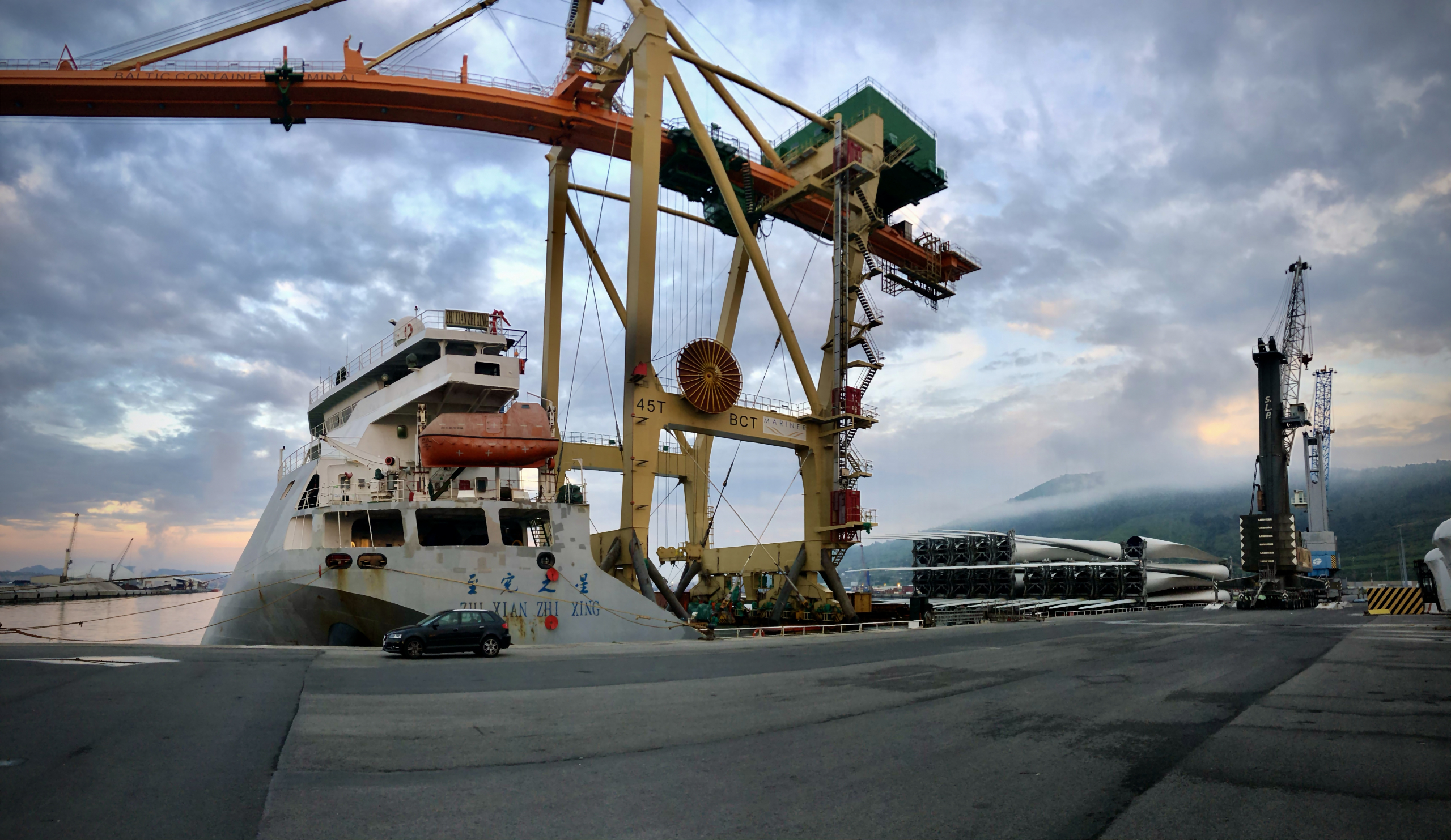
How to maximize the bollard pull capacity of a ship?
The Bollard pull (BP) is the force delivered by a ship when pulling at zero speed. It is a key requirement in the specification of tugs, AHTS, workboats and rescue vessels, to name a few.
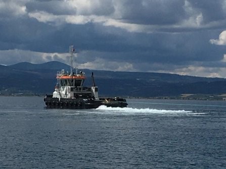
During the tests, the ship is connected with a rope or cable to a bollard on the shore, and the force exerted over the bollard is measured with a dynamometer. Each test shall last 30 s for the maximum bollard pull read, and 5 min for the averaged bollard pull value. Thus, the ship and its surroundings must be in conditions that first allow the development of full thrust, and second, that this thrust can be maintained for at least 5 minutes.
Although it seems a simple test, as it often happens in the marine industry, there is more than meets the eye. The bollard pull test must be optimized to ensure the suitability of a ship for a specific job, or sometimes to win a contract. Many vessels out there could have a higher rated thrust than what the value measured by the Class Society suggests. But for this to be true, every detail of the BP tests must be carefully considered, just like we would do if designing a unit for the America's Cup.
Trials must be performed at a location which provides a sufficient depth with unobstructed waters around the vessel. The line connecting the ship and the bollard must be out of the water during the tests, and recirculation effects shall be controlled and minimized. Currents shall also be very slow, or inexistent if possible. Even though an aft current may seem to help, currents are hardly stationary. Therefore, they will probably cause instabilities which do not allow the development of the full thrust, and in the end result in an awful averaged BP.
The integration in hulls of propellers or thrusters with a high BP requirement gets tricky as the propellers come too close to the hull or too close together. Interaction phenomena show up, and this interaction shall be carefully considered in the design of propellers, nozzles, shaft and hull. In today's jargon, we may say propellers benefit from social distancing. But sometimes this is not possible.
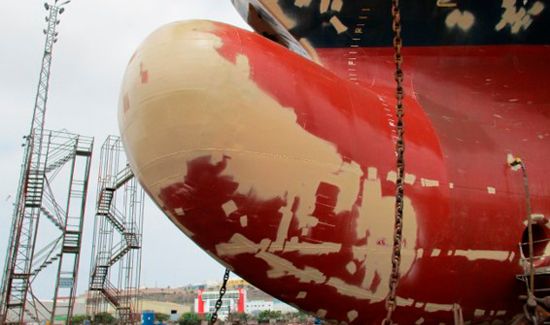
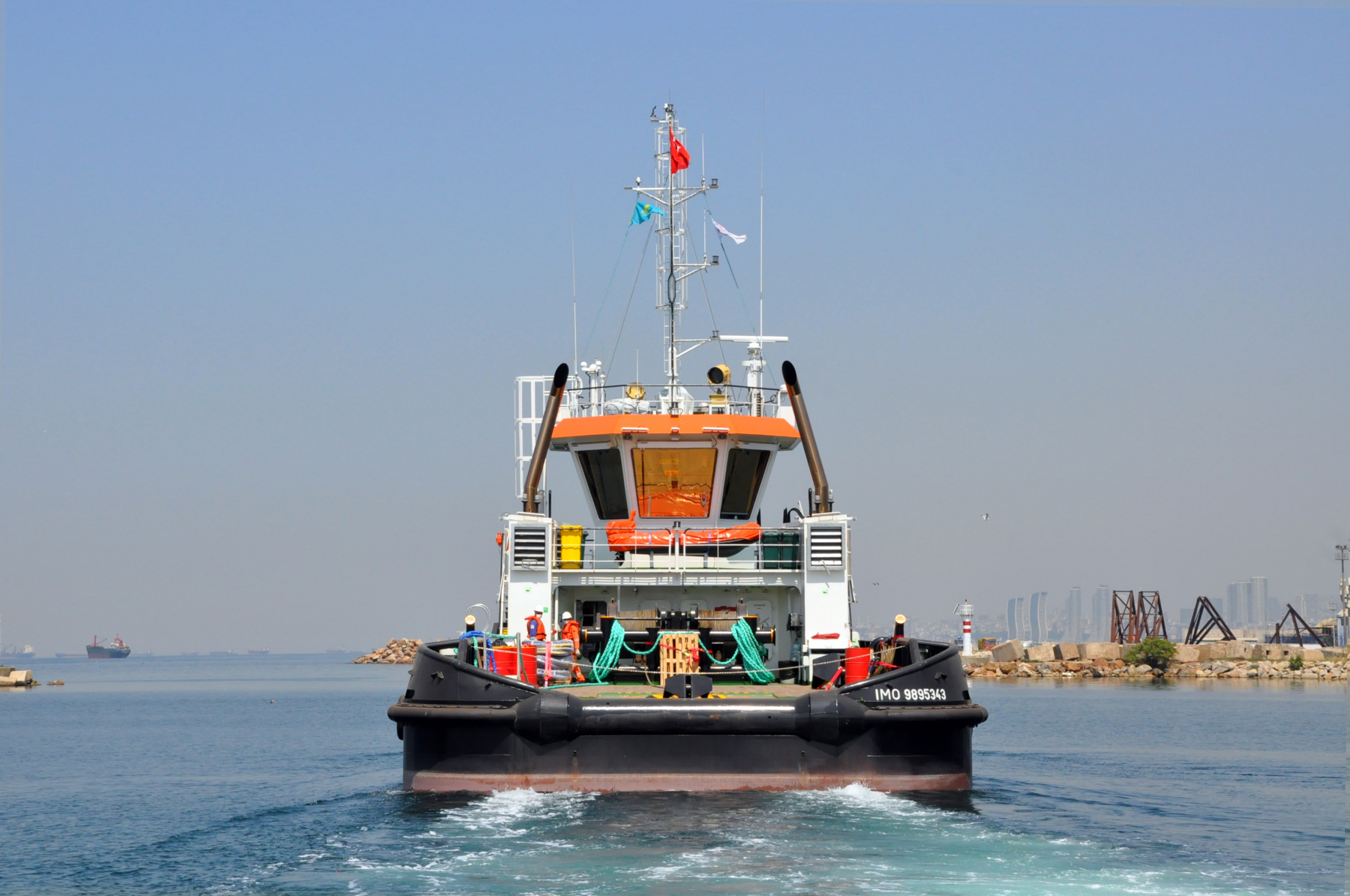
An interesting example concerns the design of ultra-shallow draft tugs (USDT) with a considerable bollard pull requirement. USDTs have, in order to exhibit a small draft, a very full hull shape (high block coefficient) with tunnels in the stern to accommodate the propellers. These propellers are within nozzles which in many cases pierce the water surface in idling conditions (when the propeller is not running). The propeller diameter is thus restricted, which increases the risk of cavitation. Fortunately, the interaction can be predicted and adjusted in preliminary design stages by performing specific CFD simulations of the hull shape interacting with the nozzle, the propeller and the appendages.
CFD simulations are able to predict hydrodynamic losses in the theorical bollard pull condition due to the hull shape, shaft elements, and the dynamic effects that may be induced by the water depth, environmental conditions or obstructions in the surroundings.
In the case of study, we designed a USDT and performed the Bollard Pull capacity prediction performing CFDs studies.
The vessel main particulars are:
-
- Power (2×969 kW)
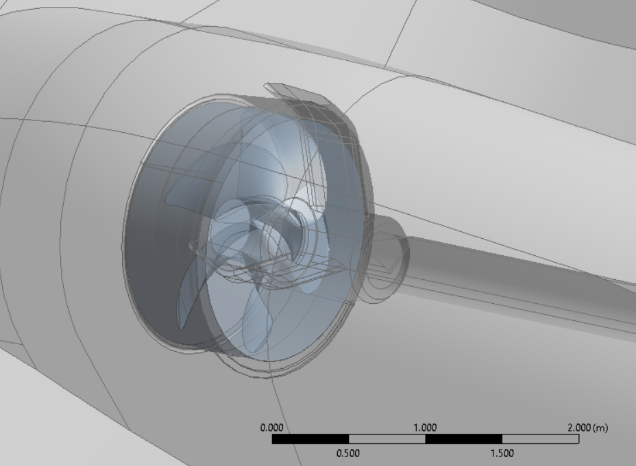
- 2 nozzle propellers: 1.6 diameter and 5 blades
- Nozzle ratio L/D=0.4
- 332 rpm (engine 1800 rpm)
- LOA = 30m
- B = 11 m
- Max speed 11 kn
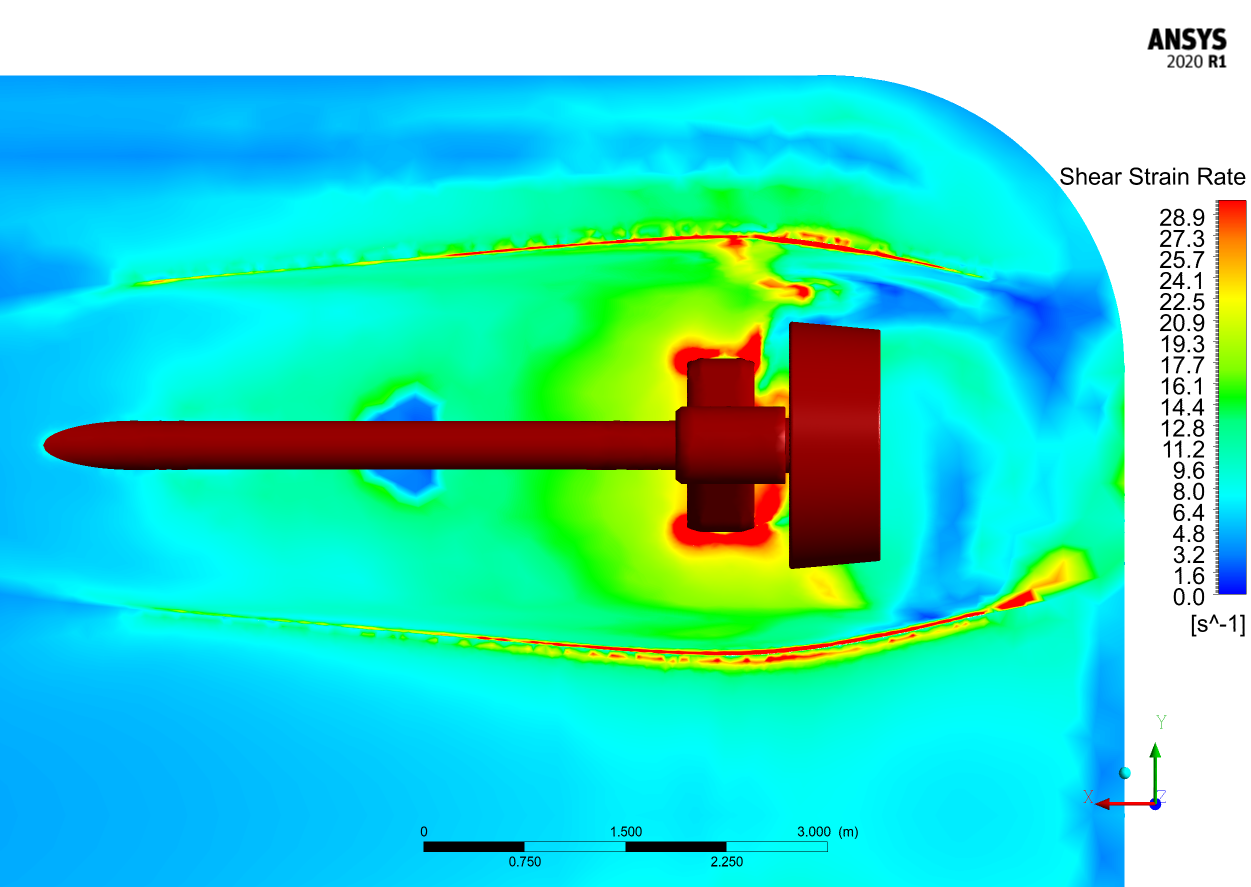
CFD simulations were performed in steady conditions with the commercial software ANSYS CFX. Runs were done with 1kn ahead speed using an SST turbulence model. Although a 1 kn ahead speed slightly reduces the BP capacity, it also helps to organize the flow in the simulation.
The first runs with CFDs helped us to quantify losses due to hull shape and its appendages. Therefore, the hull shape was faired and optimized to achieve a better performance. The BP was approximately increased by 2 t. Special recommendations were made as well to the shipyard to control and reduce shape defects in the area impacting the water flow around the propellers.
This case of study proves the importance of a thorough hydrodynamic assessment in the early design stage. The tools and experience that naval architects possess today ensure the theoretical bollard pull can be obtained with good test conditions. So, if you made it this far and read the post, you may be wondering if you can increase the BP of your current and future vessels with minor modifications. If that is the case, please do not hesitate to contact us. We surely can help.